Technology

Lithography based ceramic manufacturing.

A light engine cures a ceramic loaded slurry one layer at a time. The printed green body is then debound and sintered until it densifies. It is three operations, and the part can fail at any one of them.

40µm

Pixel size in the build plane

25µm

Standard layer height, 10 to 100 µm available

100µm

Minimum wall thickness, as sintered

60vol%

Maximum solids loading in the slurry

460nm

DLP exposure wavelength

99%

Of theoretical density, typical

Step one

Cure the slurry, layer by layer

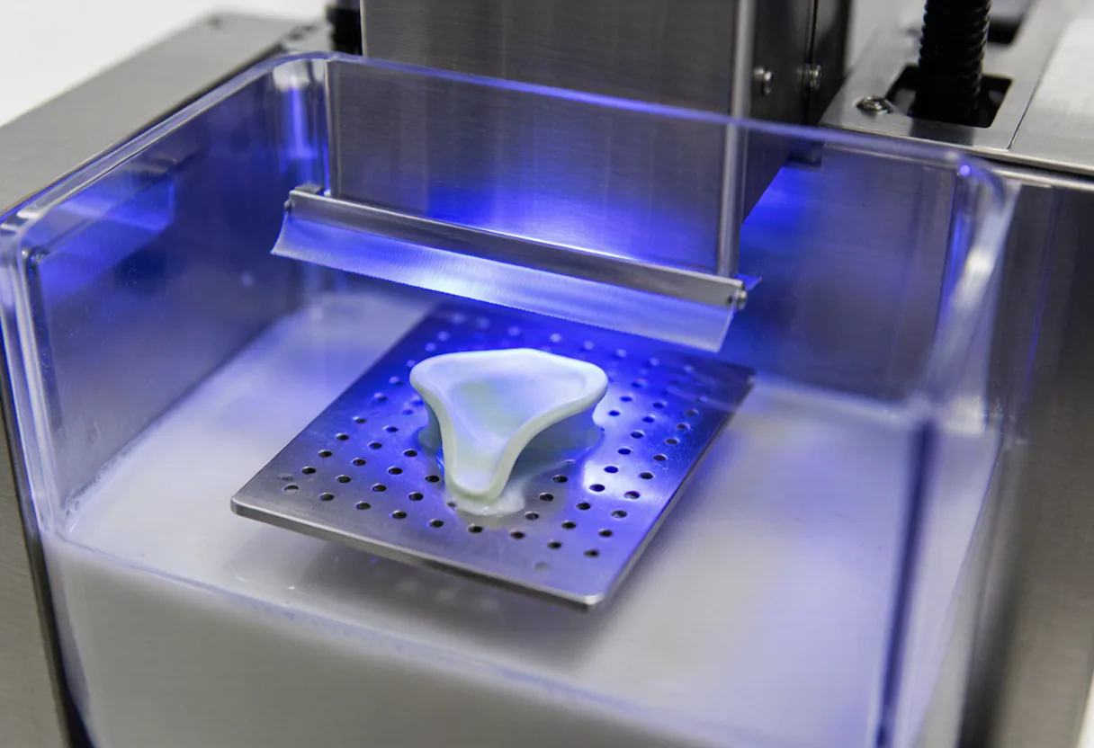
A ceramic powder is dispersed in a photocurable resin at a solids loading high enough that the part can densify later. A blade spreads the slurry across a transparent vat, the vat rotates to re-coat, and a 460 nm DLP engine exposes the cross section from below. The platform lifts, the vat tilts to release the layer, and the next one starts.

Wavelength
452 to 465 nm
Layer height
10 to 100 µm
Pixel size
40 µm
Solids loading
35 to 60 vol%
Interior of a lithography based ceramic printer with a white green part being cured through a transparent vat

Step two

Debind, then sinter

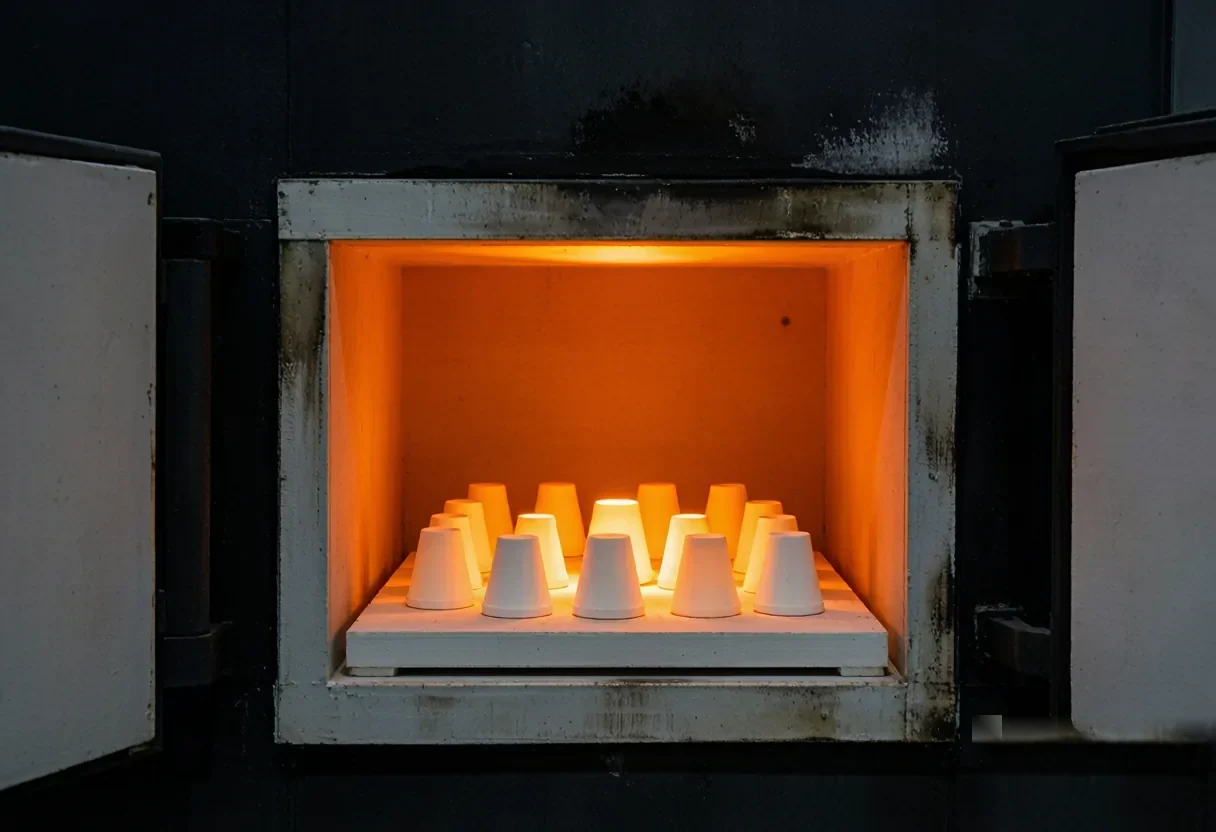
The green body is a ceramic particle held in a polymer network. Debinding burns that network out on a slow ramp, because heating too fast cracks the part long before it reaches the furnace. Sintering then fuses the particles and the part shrinks by 15 to 20% linear. Both halves of this step are the reason we model shrinkage into the build file rather than correcting afterwards.

Debind range
100 to 600 °C
Ramp rate
2 to 5 °C/min
Sinter peak
1300 to 1800 °C
Linear shrinkage
15 to 20 %
Ceramic parts glowing orange on a kiln shelf inside a high temperature sintering furnace

Step three

Measure what came out

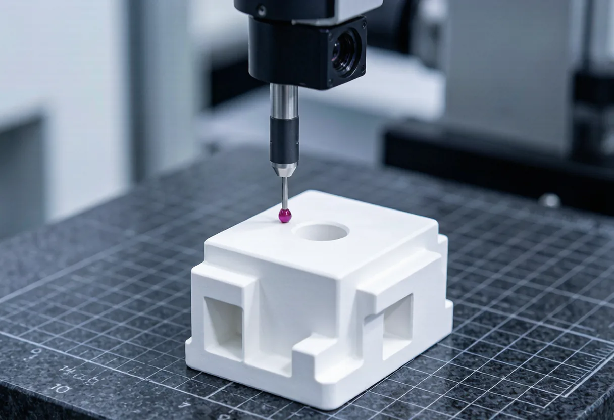
As sintered surfaces land between Ra 0.3 and 0.9 µm depending on grade, which is already smooth enough for most functional parts. Where it is not, we grind and polish. Wall thickness and internal channels get verified on optical metrology and CT, and the dimensional report goes out with the first article.

Achievable tolerance
under 40 µm
Roughness Ra
0.3 to 0.9 µm
Grinding
Optional
CT scanning
On request
Technical ceramic component being measured under an optical measuring microscope
Design rules

Design against the process, not around it.

Additive removes the tooling constraint and replaces it with four others. All four are manageable if you know them before you freeze the geometry.

Wall thickness

Thinner walls survive printing but tend to crack in debinding. For production parts we prefer 0.3 mm and up unless the geometry forces otherwise.

100 µm minimum, as sintered

Shrinkage

We scale the build file per geometry and validate against the first article. Do not pre-scale your model, send it at nominal size and we handle the compensation.

15 to 20% linear, compensated

Overhangs

Large flat spans need support structure. Contact marks are inspected after sintering and can be ground flat where the surface matters.

Supports printed, then removed

Internal channels

Conformal cooling, lattice and honeycomb structures come out in one piece. Uncured slurry is removed before firing, so closed channels need a drain path.

Where the process earns its keep

What we need from you.

A clean file and three pieces of context are enough to quote.

File

STEP keeps units and tolerances intact. STL is fine for quoting. Send the model at nominal size, we apply shrinkage compensation.

Context

Temperature, load and atmosphere decide the grade faster than anything else on the drawing. If you already have a material in mind, tell us and we will confirm or push back.

Volume

One part and a hundred parts are planned differently. Batch jobs get a fixed parameter set so the last part matches the first.

Additive advantages

Why print the part, not machine it.

Ceramic additive manufacturing removes the tooling constraint that limits every conventional route. The gains are geometric, but they also change how fast you can iterate from idea to part.

Print straight from CAD

No mould, no fixture, no tool to wear out. The file is the tool, so a revision is a new build, not a four week tooling lead.

Geometry a mill cannot reach

Internal channels, undercuts and lattices print in one piece. Conformal cooling and hollow cores come out without assembly.

Short lead time

Skip tooling entirely. First article samples land in days to weeks, not the months a mould or die would cost you.

Iterate freely

Change a wall thickness or a channel and reprint. Design loops that used to need a new tool now need a new file.

Digital and repeatable

Every parameter is logged against the order. The last part of a batch matches the first, and the next batch matches the last.

Many parts, one build

Multiple geometries share one build plate. Low volume production and spare parts print together without extra setup.

Have a geometry in mind.

Send the file and the operating conditions. We will tell you what the process can hold, and what it cannot, before you commit.

Upload a part

Quoted within two business days.

Ready to print your first part?

Upload a STEP, STL or 3MF file with your material and operating conditions. We return a price and a risk note within two business days.