CoreCera 999
Aluminium oxide, Al2O3, 99.9% pure
Density3.985 g/cm³
Bending strength, 4 pt430 MPa
Hardness HV101550
Thermal conductivity37 W/mK
Max service temperature1650 °C
Lithography based ceramic manufacturing for alumina, zirconia and silica. 99.4% of theoretical density, 40 µm tolerance, and no tooling to pay for before you know the part works.
Cores, lattices and channels that would otherwise need a mould, a five axis mill or a small miracle. We print the green part, remove the binder, then sinter it dense.
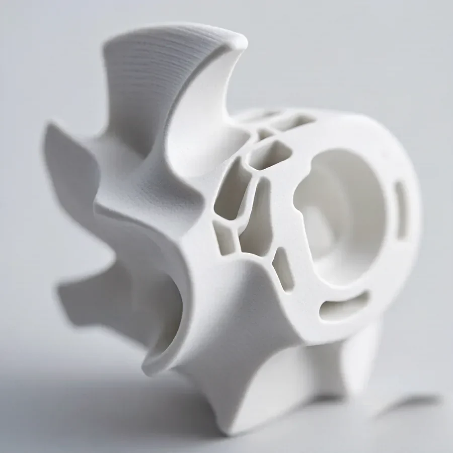
Internal cooling channels and thin walled cores for single crystal blades, then leached out after casting.
Silica based CoreCera SC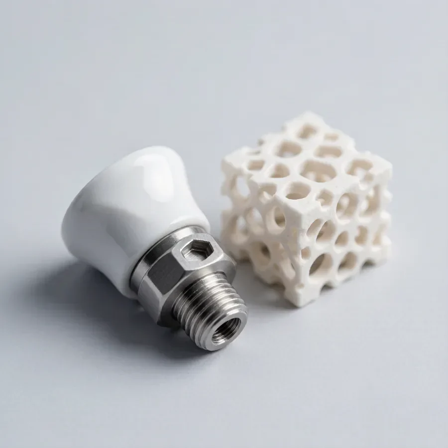
Honeycomb and gyroid structures with channel walls down to 100 µm, held uniform across the whole cross section.
Alumina and zirconia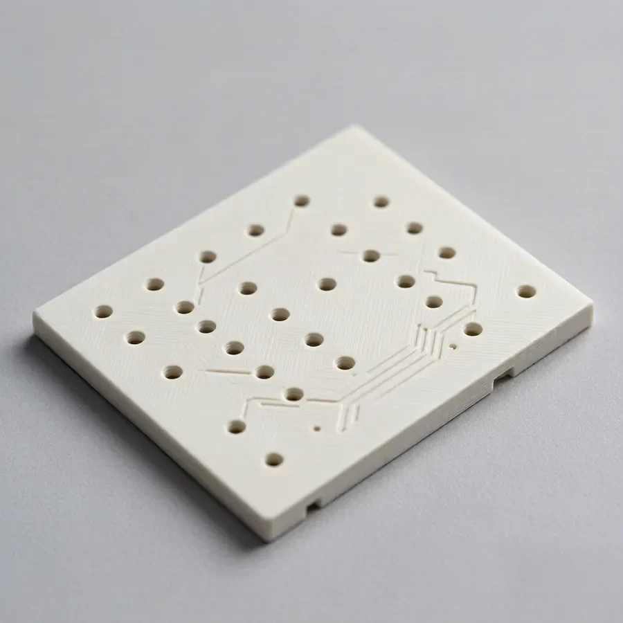
Alumina and zirconia for high voltage insulation, aluminium nitride for heat that has to leave the part, with vias and standoffs printed in the same build.
See applications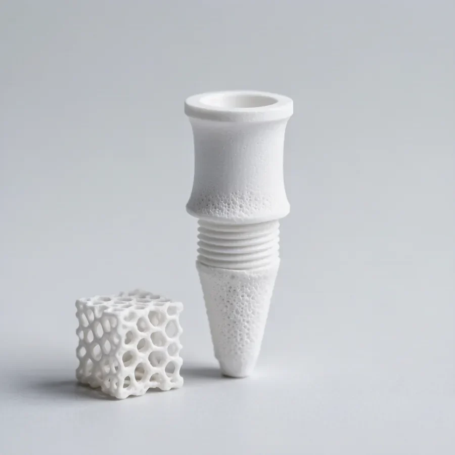
Zirconia abutments and porous bone scaffolds built from patient geometry, with controlled pore size and strut thickness.
Biocompatible zirconiaAdditive is only the first third of the job. The parts that fail usually fail in debinding or in the furnace, so that is where we spend our attention.
A 460 nm DLP engine exposes each layer through a transparent vat while a blade re-coats ceramic loaded slurry.
Organics come off on a controlled ramp so the green part does not crack before it ever reaches the furnace.
The part shrinks as it densifies. We model that compensation into the build file, geometry by geometry.
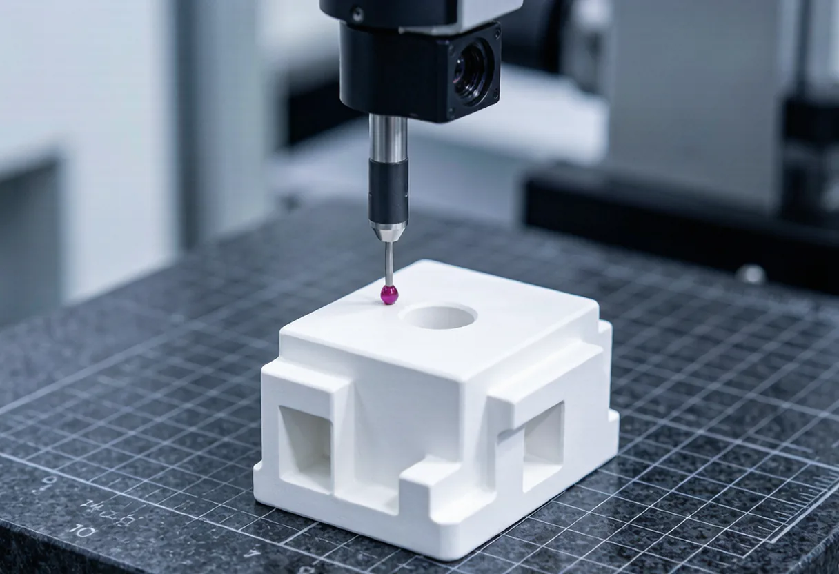
Optical metrology and CT scanning confirm wall thickness and internal channels before anything ships out.
Oxide grades we run every week, plus non-oxide grades for heat, thermal shock and wear. Every figure below is measured on printed and sintered test bodies, not borrowed from a pressed and machined data sheet.
Aluminium oxide, Al2O3, 99.9% pure
Yttria stabilised zirconia, 3 mol% Y2O3
Aluminium nitride, AlN, for moving heat
Lithography based ceramic manufacturing, specified per build rather than per brochure.
Pixel size in the build plane
Standard layer height, 10 to 100 µm available
Minimum wall thickness, as sintered
Maximum solids loading in the slurry
DLP exposure wavelength
Longest build axis
Ceramic additive manufacturing fails at the margins. Thin walls crack in debinding, shrinkage opens up tolerances, and one bad furnace cycle can undo a week of printing. Every step below is logged against your order number.
15 to 20% linear, applied in the build file and checked against the first article.
A dimensional report ships with every new geometry, before the batch runs.
Powder lot, slurry batch and furnace cycle recorded against each order.
Wall thickness and internal channels verified, not estimated.
Grade data sheets, a capabilities brochure and a design guide — free to download, no form and no email gate.
What we print, the materials we run and the industries we serve.
Wall thickness, shrinkage, overhangs and internal channels — the four rules that decide whether a geometry prints.
Where ceramic beats steel, aluminium and polymer: temperature, wear, corrosion, electrical behaviour and weight.
Upload a STEP or STL file with your material and quantity. We quote within two business days and flag any wall thickness or shrinkage risk before we print.
STEP, STP, STL, 3MF or IGES. NDA on request.
Upload a STEP, STL or 3MF file with your material and operating conditions. We return a price and a risk note within two business days.